What Is Isometric Projection?
Isometric drawing, also commonly called isometric projection. Isometric projection is a method of graphic representation of three-dimensional objects through drawing. Isometric Drawing is used by engineers, technical painters, and architects.
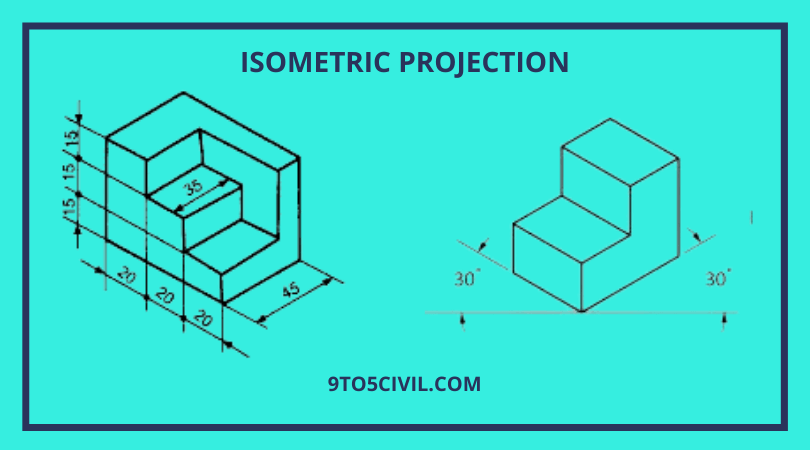
In isometric projection, the plan shows the three visible sides of the object from the same angle to each other.
Thus the isometric projection shows the sides of the object at an angle of 120 to each other. Thus these lines of the object are called isometric axes.
Lines that are not parallel to the isometric plan are called non-isometric lines.
In isometric projection, two isometric axes are held at an angle of 30 with the horizontal plane. While the third axis forms an angle of 90 with the horizontal plane.
Graphic representations of three-dimensional objects used by engineers, technical illustrators, and architects are made using the Isometric projection in engineering drawing method.
Principle of Isometric Projections

It is an illustrated orthographic projection of an object in which a transparent solid containing the object is tilted in such a way that the solid diagonal of the cube is perpendicular to a vert plane and the three axes are inclined towards the plane.
In the isometric projection of an object, the three axes of the projection passing through those solid particles of the cube form a transparent cube with a horizontal plane.
The isometric projection of the cube is shown in the figure. It shows the isometric projection of a cube by ABCDFGH points.

Isometric Scale
In isometric projection, the isometric lines for the object are drawn with an angle of 30 horizontal planes. So the length of the object is not equal to the actual length. But it is only 80 percent shorter than the actual length.
An isometric projection is formed using an isometric scale. Using this scale, the actual dimensions of the object are converted to isometric dimensions.
The isometric scale can easily be found in the reduction of the isometric line by the construction of the figure. For this, triangle DPA is formed as shown in Fig. 1. And a point is marked on it. The scale of this figure draws vertical lines to suit the isometric length.


Now D.P. the line shows the true scale. The sections of the line DA give the parameters of the isometric scale. The isometric line D.A. is shown in the figure. The sections of giving parameters to the isometric scale. The correct length of the isometric length is obtained by the ratio of the triangle ADO and PDO, above Figure 2 (Isometric cube).
DA/DP = cos 45° /cos30° = 0.816
The isometric axes are reduced in the ratio 1:0.816, i.e., 82% approximately.
Lines in Isometric Projection
The relationship between the lines of isometric projection is clear from the instructions below,
- The parallel lines on the object are parallel to the isometric projection.
- A line is drawn parallel to the isometric axis of the object. This is called the isometric line and its length is reduced by 82%.
- A line in isometric drawing that is not parallel to the isometric axis is called a non-isometric line. Shows the extent of projection of non-isometric lines. These lines are located on different planes.
- Vertical lines on an object are also vertical in isometric projection.
- Horizontal lines on an object are drawn at an angle of 30 with a horizontal line in isometric.
Also Read :
What Is Isometric Drawing?
Isometric drawing, also commonly called isometric projection. This is a method of graphic representation of three-dimensional objects through drawing. Isometric Drawing is used by engineers, technical painters, and architects.
3D isometric projection is a drawing depicting a 3D drawing. Drawing of a set of objects using a 30-degree angle. The same scale is used for each axis in isometric drawing as a type of axonometric drawing.
An isometric view shows any object or building in three different perspectives (usually the front, top, and right). Each of these 3D isometric views is drawn in 2-D (two-dimensional). And it has parameters showing the length, width, and height of objects.
After studying the basics of isometric drawing carefully, you can create a free-hand isometric drawing.
Isometric Projection Examples
The following instructions should be followed to create isometric drawings from orthographic views,
The main parameters and orthographic view of a given object are studied.

Draw isometric axes for drawing.

Drawing the main parameters of an object along the isometric axes according to their true values.

Lines parallel to the isometric axes are drawn parallel to the view of the object.

Locate the principal corners of all the features of the object on the three faces of the housing block( d).

Method of Drawing Isometric Scale
The following steps are used to draw an isometric scale,
- After drawing horizontally, two lines are drawn at 45 ° and 30 ° angles along the horizontal line.
- Do the marking according to the actual scale above the 45 ° angle line.
- Now a vertical offset is drawn from the 45 ° angle line to the 30 ° angle line. Which is known as the isometric scale
Methods of Isometric Drawing
The following is a description of two methods of drawing isometric projection
1. Box Method
This method of isometric drawing is simple. But it takes a lot of time to draw. In box method, the maximum length, width, and height of the object are noted.
These parameters are created according to the method of a box. These parameters of the box are represented as isometric projections.
Make angles of 30 and 90 degrees along the horizontal line in this way. This way the other parts of the object are displayed.
Isometric lines are drawn in this way parallel to the isometric axis. Non-isometric lines, circles, and other curves are then drawn. Extra lines are erased at the end of the drawings.
2. OffSet Method
In this method, to create an iso view, the side of the object is selected. The length and width of objects are drawn parallel to the isometric axis.
Non-isometric lines, circles, and other curves are then drawn. Extra lines are erased at the end of the drawings.
Isometric Drawing for Beginners
Using the first ruler to draw Isometric Drawing, draw a vertical line on the page, and mark three equal distances along with it. Draw a horizontal line through the lowest point, and using a protractor, draw a line with a 30-degree angle above the line on both sides. Draw a back line from the lowest point with a 30-degree angle on each side.
Also Read : What Is Salt Finish Concrete? | Specification of Salt Finish Concrete | Process of Salt Finish Concrete
Like this post? Share it with your friends!
Suggested Read –
- What Is Chain Surveying? | Principle of Chain Surveying | Instruments Used in Chain Surveying | Technical Terms of Chain Surveying | Procedure for Chain Surveying | Advantages & Disadvantages of Chains in Surveying
- What is a Short column? | What Is a Long Column? | Difference Between Short Column and Long Column
- Top Construction Companies in the USA
- What Is Concrete Frame? | What Is Precast Concrete Frames? | The Components of Concrete Framed Structures | Advantage & Disadvantage of Concrete Framed Structure
- What Is a Cantilever Bridge? | Type of Cantilever Bridges | Advantages & Disadvantages of Cantilever Bridge
Frequently Asked Questions (FAQ)
Isometric Drawing
Isometric Drawing Meaning
- Isometric drawing is also commonly called isometric projection.
- This is a method of graphic representation of three-dimensional objects through drawing.
- Isometric view Drawing is used by engineers, technical painters, and architects.
Isometric Perspective
Isometric perspective means representing a three-dimensional object in two dimensions. Isometric drawing is inappropriate for precise design, testing, and manufacture. when 3D drawings are required.
Isometric Angle
Isometric drawing is a form of 3D drawing. You must have seen Laptop and mobile phone, tablet isometric view. In which isometric drawing angle is used by setting 30-degree. Isometric view angle is a type of anometric drawing so the same scale is used for each axis, resulting in non-distortion of the image.
Orthographic and Isometric Projection
The main difference between orthographic and isometric projection is that the orthographic drawing represents a two-dimensional view of the object. And isometric drawing represents three-dimensional views of the same object.
Isometric Projection of Sphere
The isometric projection of a sphere is a circle. If you look at a sphere in any direction, you will see that its shape is a circle of radius equal to the actual radius of the sphere. Thus, the isometric drawing circle will be a circle of radius equal to the actual radius of the sphere.
Isometric to Orthographic View
Isometric: A method of representing a three-dimensional object on a flat surface. Showing the three planes of the object. Orthographic: Displays a three-dimensional object through multiple views from different planes.
Isometric Paper
Isometric paper can be used to draw 3D shapes – for example, the cube below is drawn using the dots as a guide. The vertical lines always remain vertical, but the horizontal lines are at angles. Isometric drawings can be used to show the scale of a product as well as a 3D representation.
Isometric Dot Paper
Isometric dot paper is a type of graph paper that uses dots instead of lines to create an isometric grid. This grid is used for drawing three-dimensional objects, such as cubes, pyramids, and spheres. The dots help to create consistent spacing between the lines, making it easier to achieve accurate results.