What Is Concept Drawings?
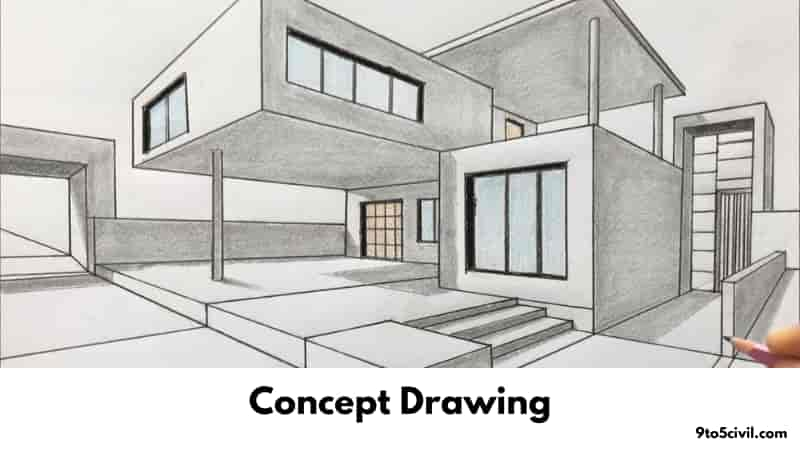
Concept drawings or sketches are a kind of freehand drawings. Used by architects, engineers, and interior designers to give initial ideas for designs in this type of drawing. This type of drawing is done in a quick and easy way. This type of drawing does not have accurate or decisive points. This drawing is a way to consider the principles of design and aesthetics.
A concept sketch is a simple sketch concept that defines various key aspects of a system. This type of drawing suggests brief but complete information.
Concept sketching is a great way to quickly display design ideas. The concept sketch provides a visual example of the basic design of an object and its layout. It also gives a concept to allow designers to design from this type of drawing before creating a detailed drawing or CAD model.
Concept of drawing allows students to create temporary sketches for their own design bikes. Students can understand where and how to use this bike through this drawing. Thus after students produce sketches, students can share the concept with the class for review and critique.
Drawing concept by focusing on the features of the object. Drawings are sometimes more clearly realized than drawings.
Drawings created by new technology such as computer-aided design or building information modeling may be restrictive in terms of accuracy. concept drawings made using pencils or pens and paper can provide a more meaningful and faster method for investigating a problem.
Concept drawings can also be used to explore various aspects of design, providing initial solutions to problems such as the layout of services, structure, method of construction, solar paths and shading, prevailing winds, method of rotation, barriers and opportunities, and possible solutions. , Establish can include aspects of the site and the relationship between them.
From concept design to an idea, or a range of ideas, the issues required for a development approach, the guiding concept and the design objective, etc., show the whole path.
Concept design refers to a sketch, ideas, and exploration, or considerable in-depth consideration, design descriptions, indicative plans, sections and locations, and a 3D model development approach.
Architecture Concept Drawing
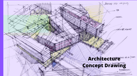
Concept drawings architecture is an idea, idea, or concept that forms the basic basis and foundation of a design project and guides the project forward. It becomes the progress of the projects and the identity of the project and is constantly advised at every stage of the development of the project.
Concept drawing architecture represents the form of the final product (complete building or structure). It has the process of developing like a seed. Thus it is the first part of the design process. It brings variety and results to the project through its various drawings.
It is used to persuade customers of the quality of the design. It also helps the building contractor to build on its foundation, and the work is done quickly and accurately. It also serves as a record of design and planned development.
Size and Scale
In architectural concept drawings, objects are represented by scale. So that the relative size can be displayed correctly. The drawing is scaled according to the size of the entire building sheet.
The dimensions of the scale drawing are measured to directly “read.”
The size of the drawing is as follows according to standard US architecture.
- ARCH A = 9 x 12 inches (228 mm x 304 mm)
- ARCH B = 12 x 18 inches (304 mm x 457 mm)
- ARCH C = 18 x 24 inches (457 mm x 609 mm)
- ARCH D = 24 x 36 inches (609 mm x 914 mm)
- ARCH E = 36 x 48 inches (914 mm x 1219 mm)
The ISO standard defines the dimensions of the paper for the paper series. Normal paper sizes are A0, A1, A2, A3, A4, A5. The table below shows the size of the paper in the series.
| Paper size | Dimensions (cm) |
| Α5 Size | 14.8 x 21 cm |
| Α4 Size | 21 x 29.7 cm |
| Α3 Size | 29.7 x 42 cm |
| Α2 Size | 42 x 59.4 cm |
| Α1 Size | 59.4 x 84.1 cm |
| Α0 Size | 84.1 x 118.9 cm |
Types of Drawings for Building Design
1. Perspective Drawing
Perspective drawing is a technique for showing perspective. This drawing is used to represent a three-dimensional object on a two-dimensional plane.
2. Scale Drawing
A drawing that shows an actual object reduced or enlarged by a certain size of an object.
Scaling is a method of drawing used to make an object larger or smaller in size, depending on the size of the drawing.
3. Production Drawing
Production drawings are various complete details of drawings, which give various details about the production of the products and the assembly.
4. Section Drawing
In ‘Section Drawing,’ ‘Section’ or ‘Sectional Drawing,’ the view of the structure is shown in such a way that it is cut into any part.
section drawing enhances understanding of structure information.
5. Site Plan
A site plan is a drawing covering a large area, which shows the full extent of the site for the proposed project. The necessary specification is also found to determine the location for the application plans. In most cases, site plans are prepared after site inspection.
6. Technical Drawing
The technical drawing is used to communicate ideas between industry and engineering. It is used to make drawings easier to understand. Most people use familiar icons, visions, units of measure, rotation systems, visual styles, and page layouts.
The need for specific communication in the preparation of a functional document is illustrated by the technical diagram.
7. Assembly Drawing
Assembly drawings are used to represent the various components present in objects.
The components show fitting with each other. And can be shown in drawing orthogonal schemes, sections, and height, or three-dimensional view, showing assembled components, etc.
8. As-Built Drawings and Record Drawing
When the construction process is complete, a built-up drawing is prepared to show the actually constructed drawing. Contractors usually mark the ‘final construction issue’ using red ink.
It is used to show the client that the construction has been completed as healthy and safe. In addition, this drawing is used to show that the construction work and maintenance are done as per the guidelines.
9. Shop Drawing
Shop drawings are drawings made for contractors, suppliers, manufacturers, subcontractors, consultants, and fabricators.
Before the creation of the product, various documents of construction, various references to drawings and specifications, etc., help the architect and engineer to draw their shop drawing.
Dimensions, product conventions, and special forged instructions should be included in the shop drawing. There should be shop drawings that employees can clearly understand.
10. Block Plan
The block plan shows the seating of the buildings according to the blocks on the map of the surrounding area. It also shows boundaries, roads, and other details.
This type of drawing indicates the site of development and access in the red outline, as well as the blue outline, indicating the land owned by the developer.
11. Construction Drawing / Working Drawing
Working drawings are used to provide dimensional, graphical information. Provides information for any project by the contractor to build the works or to assemble or install components.
12. Design Drawing
Design drawings describe the area of each component, starting with block and measuring drawings and sketches. That way will enable the construction to be quick and manageable by drawing in very detail.
Design drawings are used at an early stage to develop ideas about developing the design.
 Skip to content


